How String Inverter Architecture Impacts Energy Yield and Efficiency

String inverter architecture determines how DC power from PV modules converts to AC. The internal topology, control loop, and thermal design set the loss budget. Choosing the right architecture protects energy yield by managing voltage, current, and heat across the DC string.
- Inverter architecture sets the baseline loss budget before module efficiency is considered.
- Control topology determines how the inverter handles voltage mismatches and partial shading.
- Thermal design directly affects derating and long-term energy production.
- Sourcing decisions must match the architecture to site conditions and utility requirements.
- A worked example shows how a single mismatched module changes string behavior under a fixed architecture.
What string inverter architecture actually means
String inverter architecture refers to the internal electronic structure that turns direct current from a PV string into alternating current for the grid. It covers the power conversion stage, the control loop, the cooling path, and the protection logic. Engineers treat this structure as the system loss budget. If the architecture is weak, even premium modules lose energy at the inverter stage.
The term covers three layers. The power stage handles high voltage and high current. The control stage decides how often the inverter samples the DC bus and how it adjusts the power factor. The thermal stage moves heat from the power semiconductors to the outside air. Each layer has a different failure mode. A weak control loop causes oscillation. A weak power stage causes switching losses. A weak thermal stage causes derating.
This article focuses on the technical principles that matter to buyers. It explains how each architectural element affects energy yield and efficiency. It also shows how these choices create sourcing decisions for commercial and utility scale projects. The goal is to give engineers a clear checklist for evaluating inverter proposals.
How the DC side determines energy yield
The DC side of a string inverter is where PV modules connect to the power electronics. The inverter sees the sum of module voltages and the string current. It does not see each module individually. This creates a direct link between the DC architecture and the AC output.
The maximum power point tracker adjusts the operating point of the string. It moves the operating point along the PV curve to extract the most power available. The tracker works against the inverter power stage. If the power stage cannot handle the voltage range, the tracker has less room to operate. If the control loop is slow, the tracker misses small changes in irradiance.
A common mistake in sourcing is treating the inverter as a black box. The DC input range is a specification, but the architecture inside decides how that range is used. An inverter with a wide voltage window but a slow control loop may still underperform. A narrow window with a fast loop may perform well in stable conditions but fail during transitions.
The string current also matters. The inverter must handle the current from the entire string without excessive conduction loss. The power stage uses IGBTs or MOSFETs. The switching frequency and gate drive design determine the loss per cycle. Higher switching frequency can reduce passive component size but increases switching loss. The architecture must balance these two effects.
How AC conversion topology affects efficiency
The AC side converts DC power to grid synchronized AC. The topology used inside the inverter determines the number of power switching events. A two level topology uses two switches per leg. A three level topology uses more switches but can reduce voltage stress on each switch. The choice affects the loss profile.
Two level inverters are common in string applications because they are simpler and cheaper. They use a standard bridge structure. The switches see the full DC bus voltage. This increases the voltage stress on the semiconductors. The loss per switching event is proportional to the voltage and current. At high DC bus voltages, this loss becomes significant.
Three level inverters distribute the voltage across multiple switching states. Each switch sees a lower voltage stress. This can reduce switching loss and allow higher switching frequencies. The trade off is complexity. More switches mean more gate drivers, more protection logic, and a larger control board. The cost increase must be justified by the energy gain over the inverter life.
The grid connection stage also matters. The inverter must synchronize with the grid frequency and phase. The control loop uses phase locked loop logic to lock onto the grid. A well designed loop tracks small frequency drift without introducing phase error. A poorly designed loop can cause power factor errors and harmonic distortion. The utility grid code sets limits on these values. The inverter architecture must be able to meet them without excessive external filtering.
How control logic handles shading and mismatch
Partial shading is the most common cause of string level energy loss. When one module in a string is shaded, its voltage drops. The string current is set by the weakest module. The rest of the string operates at a lower power point. The inverter sees a reduced string voltage and a reduced power output.
The inverter control loop responds to this change. It adjusts the maximum power point tracker to find the new operating point. The speed of the response matters. If the loop is slow, the inverter stays near the old operating point during the transition. This creates a temporary loss. The longer the shading event, the larger the total loss.
Shading also changes the voltage distribution across the string. The inverter does not know which module is shaded. It only sees the total string voltage. The architecture can include a monitoring stage that samples individual module voltages. This requires extra wiring and extra electronics. It allows the inverter to identify the shaded module and adjust the control logic accordingly.
A practical example helps. Consider a commercial rooftop array with a west facing roof. The afternoon sun hits the array at a low angle. A tree branch casts a shadow over a few modules in the middle of a string. The string voltage drops. The inverter tracker moves the operating point to the right. The output power falls. If the inverter has a fast control loop, it tracks the change within a few seconds. If the loop is slow, it takes longer. The energy lost during the transition depends on the loop speed and the duration of the shading.
How thermal design changes long term efficiency
The inverter power stage generates heat. The heat must move from the semiconductor junction to the outside air. The thermal design path determines how much heat the inverter can remove. If the heat removal is insufficient, the inverter temperature rises. The inverter then derates its output power to protect the semiconductors.
Derating is a direct loss of energy yield. The inverter specification sheet lists a maximum operating temperature. The inverter may be rated for a lower power output at high ambient temperatures. The thermal design uses heat sinks, fans, and enclosures. The fan speed control affects noise and power consumption. The enclosure material affects heat transfer. The airflow path inside the cabinet is critical.
A common mistake is assuming the inverter will operate at full power in all conditions. The site ambient temperature matters. A desert site has high ambient temperatures and high irradiance. The inverter may run at full power during the day but derate during the hottest hours. A coastal site may have lower ambient temperatures but higher humidity. Humidity affects the insulation and the cooling efficiency. The thermal architecture must match the site conditions.
The long term efficiency of the inverter also depends on the degradation of the power stage. The power semiconductors degrade over time. The loss per switching event increases. The inverter may not deliver the same efficiency at year ten as it did at year one. The thermal design helps slow this degradation. A cooler semiconductor junction ages slower. This is a subtle but real factor in energy yield over the project life.
How architecture affects sourcing and system design
Sourcing a string inverter means choosing the architecture that fits the site. The buyer must look beyond the nameplate power rating. The inverter data sheet lists the DC voltage range, the AC power rating, and the efficiency curve. It does not always list the control loop speed or the thermal derating curve. The buyer must ask for these details.
The utility grid code sets the requirements. The inverter must meet the grid frequency ride through rules. It must meet the power factor limits. It must meet the harmonic limits. The architecture must be able to meet these rules without external equipment. A two level inverter may need an external capacitor bank to meet the power factor requirement. A three level inverter may meet the requirement internally. The cost of the external equipment must be included in the total system cost.
The PV system design also depends on the inverter architecture. The string voltage must fit within the inverter DC input range. The string current must fit within the inverter DC input limit. The number of strings per inverter must fit within the inverter string count. The inverter architecture sets the limits. The PV design must fit within those limits.
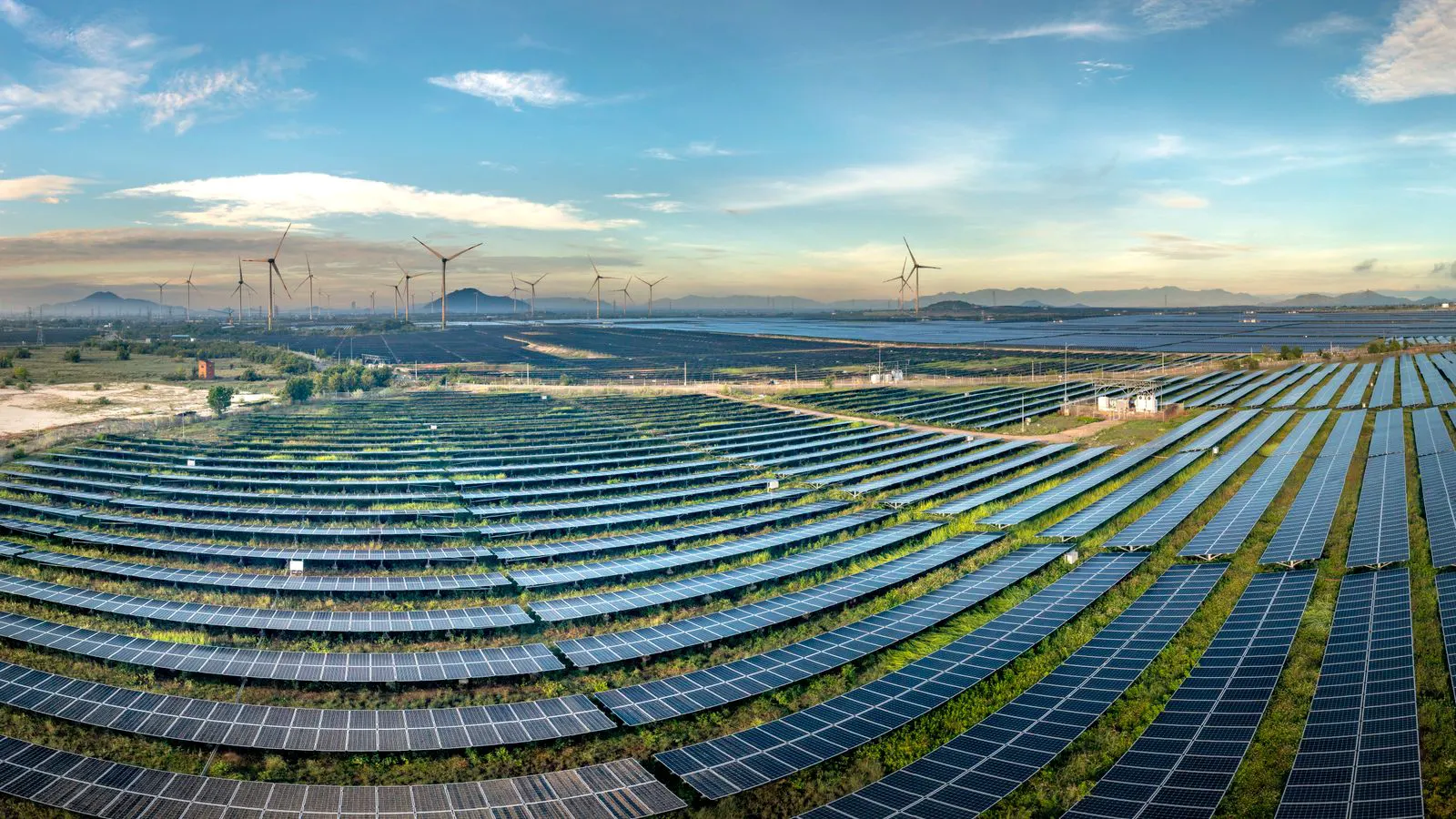
A worked example shows the interaction. Consider a utility scale solar project. The site has a large array with many strings. The inverter architecture is a two level topology with a fast control loop. The inverter has a wide DC voltage range. The PV design uses long strings to reduce the number of inverter inputs. The inverter thermal design uses a forced air cooling path. The site has high ambient temperatures. The inverter derates at high temperatures. The total energy yield is lower than a system with a three level topology and a better thermal design. The difference is small but measurable. The sourcing decision must account for this difference.
How to evaluate inverter architecture in a proposal
When evaluating an inverter proposal, look at the architecture in three parts. The power stage determines the loss budget. The control stage determines the tracking speed. The thermal stage determines the derating. The buyer should ask for the efficiency curve at different DC bus voltages. The buyer should ask for the thermal derating curve. The buyer should ask for the control loop response time.
The inverter data sheet is the first source. It lists the efficiency at different load levels. It lists the DC voltage range. It lists the AC power rating. It does not always list the internal topology. The buyer must ask the supplier for the topology details. The supplier may provide a block diagram. The block diagram shows the power stage, the control stage, and the thermal stage.
The site conditions are the second source. The site ambient temperature, the irradiance, and the shading pattern are the inputs. The inverter architecture must match these inputs. A site with high ambient temperatures needs a strong thermal design. A site with frequent shading needs a fast control loop. A site with a high voltage PV system needs a power stage that can handle the voltage.
The utility grid code is the third source. The grid code sets the limits on frequency, phase, power factor, and harmonics. The inverter architecture must meet these limits. The buyer should ask for the inverter grid compliance report. The report shows how the inverter behaves under grid faults. It shows how the inverter responds to frequency deviations. It shows how the inverter maintains power factor under different load conditions.
The architecture is not a single choice. It is a combination of design decisions. Each decision affects the energy yield and the efficiency. The buyer must evaluate each decision in the context of the site and the utility requirements. The goal is to choose the architecture that delivers the most energy over the project life. The inverter architecture is the key factor in that decision.
Frequently asked questions
What is the main difference between string inverter architecture and central inverter architecture?
String inverter architecture handles multiple PV strings with multiple maximum power point trackers. Central inverter architecture handles a single large DC bus with one tracker. The string design gives more control over shading. The central design is simpler and cheaper per watt.
How does inverter topology affect energy yield?
The topology determines the number of switching events per cycle. More switching events can increase loss but can also reduce voltage stress. The net effect depends on the DC bus voltage and the control loop speed. A well matched topology reduces losses and improves yield.
Why does thermal derating matter for energy yield?
Derating reduces the inverter output power when the temperature is high. The inverter protects the power stage by lowering the current. The energy lost during derating adds up over the project life. A strong thermal design reduces the time the inverter spends at reduced power.
How do I know if an inverter control loop is fast enough?
Ask the supplier for the maximum power point tracker response time. The response time is the time it takes for the inverter to reach the new operating point after a change in irradiance. A fast loop reduces the energy lost during transitions. A slow loop increases the loss.
Does the inverter architecture affect the utility grid compliance?
Yes. The architecture determines how the inverter responds to grid frequency deviations and power factor changes. A two level inverter may need external equipment to meet the grid code. A three level inverter may meet the code internally. The architecture must match the grid requirements.