Checklist for Installing String Inverters in Utility Scale Solar
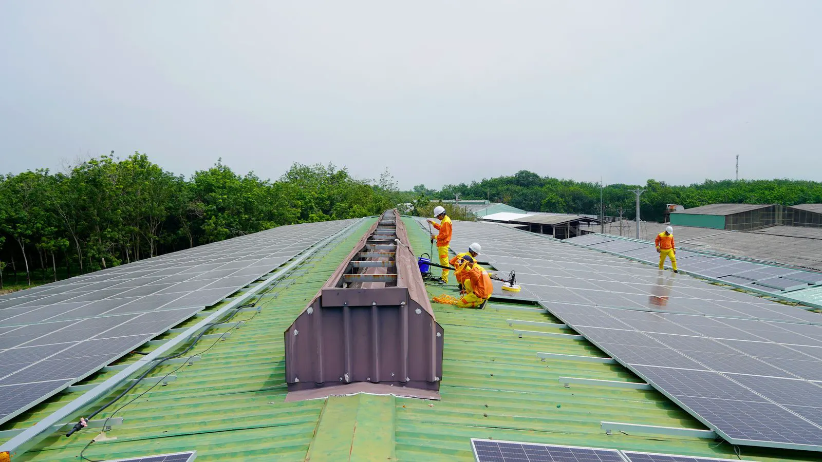
This guide provides a structured, copyable checklist for installing string inverters in utility scale solar. It covers site preparation, electrical design, grid compliance, and commissioning to reduce delays and ensure safe, compliant operation.
- Confirm inverter stringing ratios match the actual array design before ordering cabinets and mounting hardware.
- Verify all electrical clearances, grounding, and conduit paths against local utility interconnection requirements.
- Document every commissioning test, including insulation resistance, polarity, and protection device settings, for the operations team.
- Coordinate the startup sequence with the utility to avoid backfeed, reverse power, or grid synchronization errors.
Prepare the site layout and access routes
Confirm the physical location of every string inverter cabinet before the crane and concrete crew arrive. A string inverter installation at utility scale depends on predictable placement. The cabinets need level pads, drainage away from the base, and enough clearance for the maintenance team to open doors and inspect relays.
Check the distance from the inverter to the DC combiner area. Long DC runs increase cable cost and voltage drop. Keep the DC conductors as short as practical. If the distance is long, verify the cable size against the inverter maximum DC current and the allowable voltage drop at full sun.
Red flag: The site plan shows inverter cabinets in a low spot where rainwater pools. Water entering the enclosure or corroding the terminal blocks can trigger nuisance trips or insulation faults.
Review the electrical design and stringing ratios
The inverter must be sized for the actual number of strings and the maximum DC current. A string inverter accepts multiple DC inputs, each from a group of modules connected in series. Confirm the module wattage, voltage under standard test conditions, and the number of modules per string.
Calculate the string voltage at low temperature. Cold mornings push the module voltage higher. If the string voltage exceeds the inverter maximum DC voltage, the inverter may shut down or damage the power electronics. Use the manufacturer data sheet and apply a temperature derating.
Confirm the stringing ratio. If the inverter has twelve DC inputs and the design uses twelve strings, the ratio is one to one. If the design uses sixteen strings, you need two cabinets or a different configuration. Mismatched ratios create imbalance and reduce energy yield.
Red flag: The design uses a single string of modules with very low voltage, near the inverter minimum. At low irradiance or high temperature, the inverter may not reach the MPPT threshold and will not produce power.
Check grid interconnection and protection settings
Coordinate with the utility before wiring the AC side. The utility provides the point of interconnection, the required disconnects, and the protection device settings. A string inverter must not backfeed the utility when the grid is down.
Inspect the AC disconnect and the utility disconnect. Both must be visible, accessible, and labeled. The utility disconnect is usually on the utility side and locked out during installation. The site disconnect is on the inverter side and used for maintenance.
Verify the protection device type. Some utilities require a fuse, a circuit breaker, or a combination. The inverter internal protection must be compatible with the external device. If the inverter has an internal breaker, confirm the external fuse or breaker is sized to trip before the inverter internal breaker does.
Red flag: The utility disconnect is locked with a padlock that the installer does not have a key for. Do not bypass or remove the lock. Stop work and contact the utility or the owner for access.
Install the DC and AC conductors
Run the DC cables from the module strings to the inverter DC terminals. Use the correct cable size and voltage rating. DC cables must be marked as direct current. Some jurisdictions require a specific color, often red and black, or a label on the cable sheath.
Keep the positive and negative conductors separated. If they are bundled, use a barrier or a marked conduit. The polarity must be correct at the inverter terminal. Reversing polarity can damage the inverter immediately.
Install the AC cables from the inverter AC terminals to the AC disconnect. Use the correct cable size for the inverter AC output current. The inverter nameplate lists the maximum AC output. Size the cable for the continuous current, not the peak.
Red flag: The DC cable insulation is cut or pinched during the pull. A small cut in the insulation can cause a short circuit later. Inspect every cable after it is installed.
Grounding and bonding
Ground the inverter enclosure, the cabinet, the conduit, and any metal support. The ground connection must be continuous and low impedance. Use a dedicated ground conductor to the utility ground bus. Do not rely on the neutral conductor for grounding.
Bond the DC system ground if the design requires it. Some string inverter designs use an isolated DC ground, while others bond the DC negative to the AC ground. Follow the manufacturer instructions and the local electrical code.
Check the grounding resistance. A low resistance is required. If the ground is high resistance, the fault current may not trip the protection device in time.
Red flag: The ground bar is loose or the ground lug is not torqued to specification. A high resistance ground connection can cause nuisance trips or a failure to trip during a fault.
Commissioning and startup
Before energizing the inverter, verify every connection. Check the terminal torque. A loose terminal can overheat and create a fire risk. Use a torque wrench and follow the manufacturer specification.
Set the inverter parameters. Enter the grid voltage, the grid frequency, the inverter power rating, and the protection settings. These values must match the utility interconnection agreement. Do not guess.
Perform the insulation resistance test. Measure the insulation between the DC positive, DC negative, and ground. The reading must be above the manufacturer minimum. A low reading indicates moisture, damage, or a short.
Red flag: The inverter fault code indicates a ground fault after the insulation test passes. Recheck the grounding and the cable insulation. A ground fault can be caused by a damaged cable or a moisture ingress into the enclosure.
Documentation and handover
Provide the operations team with a complete set of documents. Include the site plan, the electrical single line diagram, the inverter parameters, the protection settings, and the commissioning test results.
Label every cable at both ends. Use the same label on the inverter terminal and the combiner or disconnect. This saves time during maintenance.
Train the operations staff on the inverter interface. Show them how to read fault codes, how to reset a fault, and how to take the inverter offline for maintenance.
Red flag: The operations team does not have the inverter manual or the site plan. Without these documents, a fault during a storm can cause a long outage.
Typical installation errors to avoid
| Error | Consequence | Prevention |
|---|---|---|
| Incorrect string voltage | Inverter shutdown or damage | Verify string voltage at low temperature |
| Loose terminal torque | Overheating and fire risk | Torque all terminals to specification |
| Missing or loose ground | Nuisance trips or failure to trip | Check ground resistance and torque |
| Wrong cable size | Voltage drop and reduced yield | Size cables for continuous current |
| Incorrect inverter parameters | Protection misoperation | Enter parameters from the utility agreement |
Final verification before grid connection
Before the utility energizes the grid, perform a final walk-through. Confirm all covers are closed and latched. Confirm all ladders are removed. Confirm all tools are collected.
Check that the inverter is in the correct mode. The inverter must be set to grid-tied mode, not standalone mode. In grid-tied mode, the inverter synchronizes with the grid. In standalone mode, it may attempt to feed the grid without synchronization and cause a fault.
Confirm the utility disconnect is in the off position before the inverter is energized. The inverter must not see a live grid when it starts up.
Red flag: The inverter is in standalone mode when the grid is connected. The inverter may attempt to synchronize and fail, or it may feed the grid without synchronization and damage the grid equipment.
Post-commissioning monitoring
After the inverter is connected to the grid, monitor the first few days of operation. Check the inverter interface for fault codes. Check the power output. Compare the power output to the expected value based on the irradiance and the temperature.
Check the DC and AC power ratio. The ratio should be close to one. A low ratio can indicate shading, soiling, or a string fault. A high ratio can indicate a measurement error or a grid constraint.
Red flag: The inverter output is lower than expected for the first day. Check the string voltages and the irradiance. A low output can indicate a shading issue or a module fault.
Frequently asked questions
How many modules can be connected to a single string inverter input?
The number of modules per string is limited by the inverter maximum DC voltage and the minimum DC voltage. Check the manufacturer data sheet for the exact limits.
What is the difference between a string inverter and a central inverter?
A string inverter converts DC to AC at the module or string level. A central inverter converts DC to AC at a larger scale, usually at the substation. String inverters provide better monitoring and lower voltage drop.
Can a string inverter be used in a utility scale project?
Yes. String inverters are used in utility scale projects. They are often chosen for their modularity and ease of maintenance.
How long does a string inverter installation take?
The installation time depends on the site size and the number of inverters. A small site may take a few days. A large site may take several weeks.
What should I do if the inverter shows a fault code?
Read the fault code in the inverter manual. Check the related circuit. If the fault is not obvious, contact the inverter manufacturer or the system integrator. Do not reset the fault repeatedly without understanding the cause.